Perhaps at least half-answering my previous query...
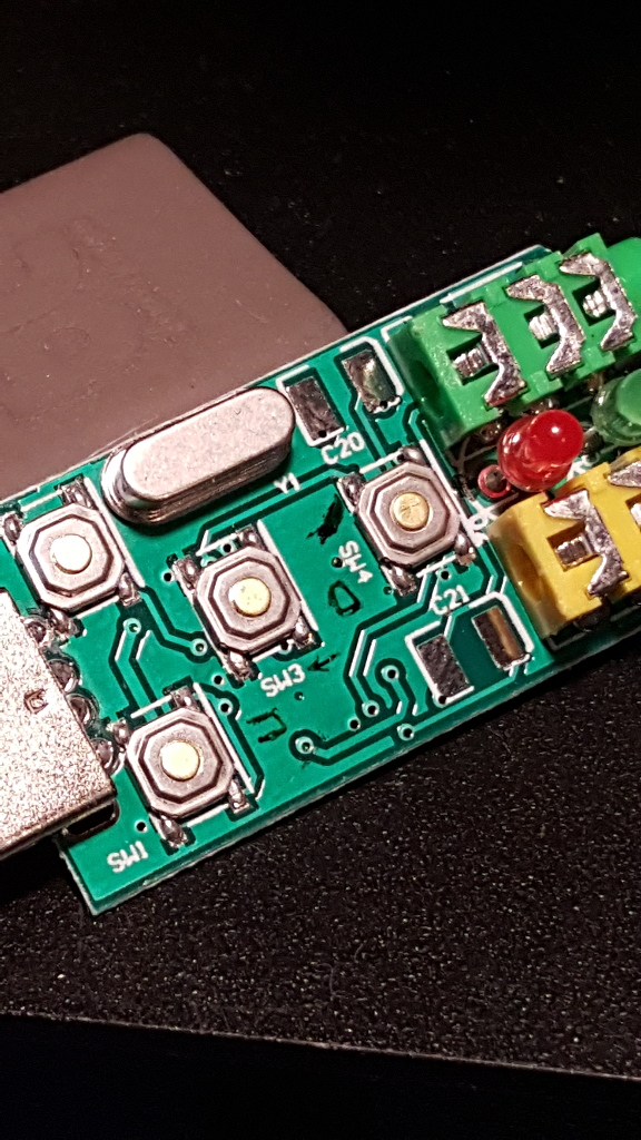
This is what I recently bought - the die-on-board version:
Anticipating this interface scheme will work:
we may be able to extrapolate some updates... I did verify the pinout of the 108 and 119 chips are the same.
Internally:
Regardless of direct/specific pin access, if the controls/indicators are assumed the same, access to the associated signals should be available at the respective (VolUp, VolDn) switches and Red LED.
The audio jacks are through-hole mount. Potentially removable and place DC blocking/coupling caps in the dongle, as well as the PTT output buffer, and perhaps any buffer for the active-low CTCSS and COS inputs.
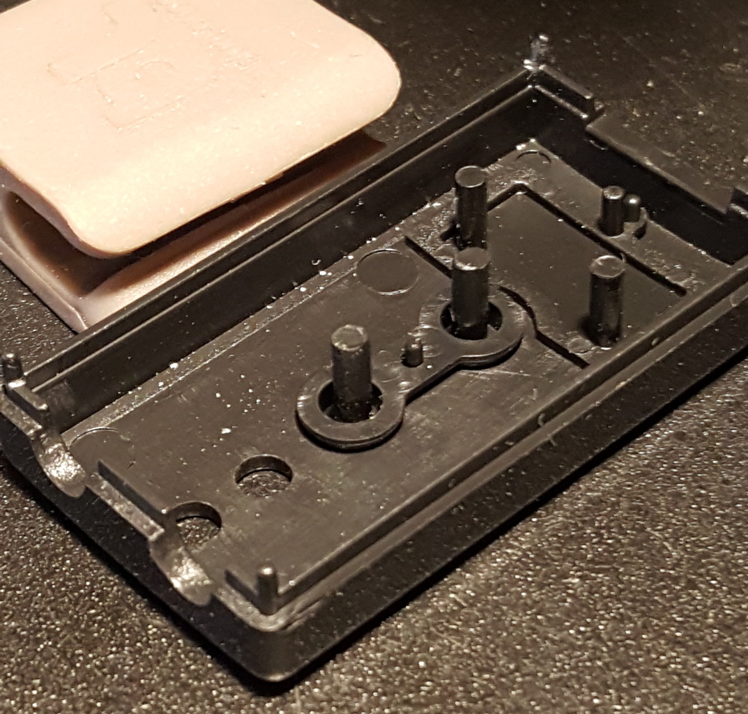
To make a little more space and not chance an erroneous, unnecessary button press, clip the actuator posts and glue the button tops in place.
Button posts:
It may be a few days before I can get to the necessary 'surgery', create a new node and test, but this looks to have potential.