
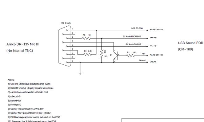
Good afternoon all, I run the MB7IIP node in the UK and at present have an Alinco in 9600 Baud running my node. The USB mod on the key fob works great and I would like to add a 70cm link. The radio is a Yaesu VX 2000 can someone give us a hand with the connectivity of this radio and the changes to my USB config please. I have included the wire code I have and the wire code of the VX2000. I have swapped the TX RX over as this seemed to me as the only change needed but still nothing from DTMF. I can go into asterisk and force a ptt as a console command and the radio will then PTT help now needed as I have tried most of last night and today. Many thanks for any help Details are: The Alinco is wired as follows and I have flat audio set on key fob plus key fob is sorting CTCSS : The Yaesu VX2000 is as follows as this too has a 9 pin connector on the rear of the radio. The radio is set in DFLT mode at the moment. Pin Signal Default and Alternate Configurations, Signal Levels, Notes 1 Squelch Output High level (5VDC / 47 kOhms) when carrier received. This does NOT care about any kind of coded squelch, just RF signal. 2 Receive Audio Output DFLT - De-emphasized Audio Output: 100mV, 10 kOhm. The output level is fixed at the factory by having no jumper at JP1003 and soldering the jumper at JP1002 on the Main unit. ALT - Flat (not De-Emphasized) Unmuted Audio Output: 250mV, 10 kOhm. Unsolder the jumper at JP1002 and solder a jumper at JP1003 on the Main unit. 3 Transmit Audio Input DFLT - Pre-Emphasized / IDC / Splatter Filtered Audio Input: 2.5mV, 600 Ohm. This input is fixed at the factory by attaching capacitor C1254 across JP1005 and soldering a jumper at JP1004 on the Main unit. ALT - Flat (not Pre-Emphasized) Audio Input: 650mV, 10 kOhm. Remove the jumper at JP1004 and solder a jumper across JP1005 on the Main unit. 4 Not Used 5 Ground Signal ground. 6 Auxiliary Output DFLT - Not Used. No jumper across JP1001 on the Main unit. ALT - Accessory Output: Open Connector Output. 'A' lamp On: Low, 'A' lamp Off: Open. Maximum voltage: 13.8V. Maximum sink current: 5mA. Solder a jumper at JP1001 on the MAIN Unit. 7 PTT Input Ground for TX, float for RX. 8 +5VDC Switched and regulated 5VDC at 50mA. 9 Not Used I hope someone can assist in the wire code changes from the Alinco to the VX2000. If whomever can help explains that the VX2000 would work better if I change to the ALT method I am happy to make the changes. Once again many thanks K Handscombe www.handscombe.co.uk

participants (1)
-
 keith handscombe